The growth of telemedicine has revolutionized the healthcare industry, giving the healthcare sector the ability to reach patients anywhere, anytime with minimal friction by utilizing remote connectivity solutions. However, the success of telehealth hinges not only on qualified providers and patient demand, but also on the strength of the underlying IT infrastructure that supports it.
For IT professionals and decision-makers, the challenge is clear: if your network isn’t built to handle high-bandwidth, low-latency telehealth services, now is the time to assess whether your infrastructure is up to the task.
https://www.inc-installs.com/wp-content/uploads/2026/04/INC-Installs-Web-Logo.png00ncrossland ncrosslandhttps://www.inc-installs.com/wp-content/uploads/2026/04/INC-Installs-Web-Logo.pngncrossland ncrossland2025-07-22 14:05:372025-07-22 14:06:38Can Your IT Infrastructure Support Telemedicine?
As businesses grow and evolve, so does the complexity of their IT infrastructure. In today’s environment, a reliable and scalable network is a necessity. One of the most effective ways to future-proof and simplify your IT systems is by standardizing your network with structured cabling. Whether your infrastructure depends on copper-based connections, high-speed fiber optics, or low-voltage systems for point-of-sale and other business functions, structured cabling provides a solid foundation for operational efficiency and long-term growth.
https://www.inc-installs.com/wp-content/uploads/2026/04/INC-Installs-Web-Logo.png00ncrossland ncrosslandhttps://www.inc-installs.com/wp-content/uploads/2026/04/INC-Installs-Web-Logo.pngncrossland ncrossland2025-07-10 12:49:282025-07-10 12:50:03The Benefits of Standardizing Your Business IT Network with Structured Cabling
The demarcation point (demarc) is the dividing line where your service provider’s equipment connects with your own. This spot determines who is responsible for the installation and maintenance of cabling and hardware. Equipment located before the demarc is the service provider’s responsibility. For any equipment located past the demarc, installations and repairs become your responsibility.
Demarcation point is typically abbreviated as “demarc” but has a few other names. Demarc is can be abbreviated as DMARC or a similar acronym. The acronym MPOE (minimum/main point-of-entry) can also refer to a demarcation point. Specifically, MPOE is the physical location where the equipment you own starts running.
Where Can I Find My Demarc?
Demarcs can be located either outdoors or indoors, typically in a location easily accessible to technicians. Common locations for a demarc include:
The outside wall of a building.
Inside the building near an electrical panel.
On an inside wall adjacent to where the phone line enters the house.
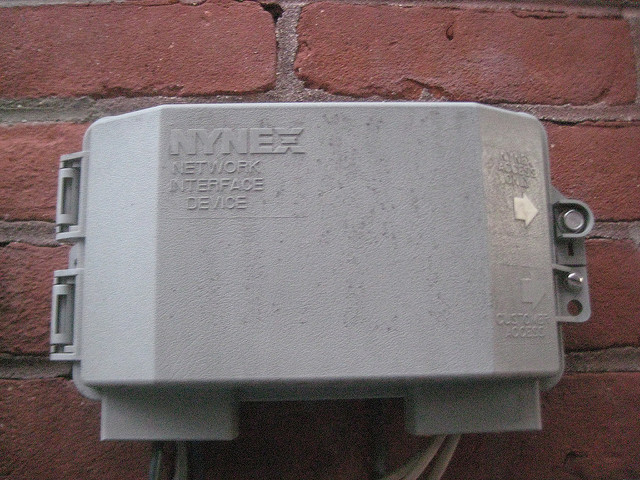
A common outdoor demarc mounted on a brick wall.
The exact location of the demarc point and related equipment often depends on the age of its installation. For example, a newer demarc mounted on an outside wall is commonly on the other side of the wall from a telephone jack. This may even be the demarcs test jack, one of the key features of any demarc.
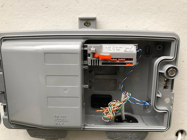
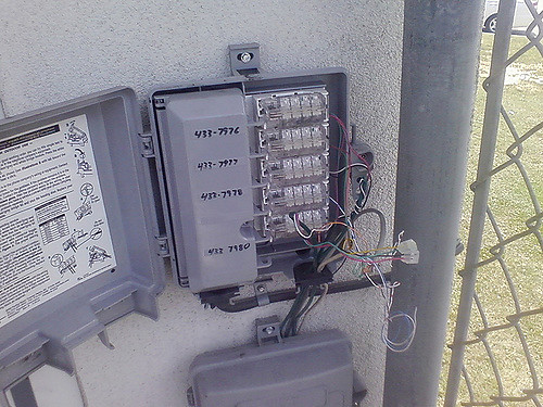
A demarc for a single phone line (left) compared to a unit holding many lines (right).
Types of Demarcs
Network Interface Device (NID)
The network interface device (NID) is another name for the box that serves as a demarc. Of the various types of demarcs, a NID is the most basic. NIDs are commonly located outdoors, giving technicians 24/7 access. These boxes are small and weatherproof with various ratings set in place by the FCC.
Equipment for a NID is fairly basic, being a “dumb” system with no digital functionality. A standard NID includes wiring termination, a test jack, and circuit protection. Circuit protection is especially critical, allowing NID boxes to act as surge protectors for your building’s wiring. This is crucial for protecting wiring, equipment, and people from the electricity normally running through the lines as well as any excess energy, which can be anything from small power surges to lightning strikes.
The level of weatherproofing for a NID is classified into three different sections by the Telcordia GR-49: normal, severe, and flooded.
Normal conditions cover the weather in most areas where people live. This includes temperature ranges from -4 to 90 °F (-20 to 32 °C) with relative humidity below 90%. Contamination is not expected in areas where these boxes are used.
Severe conditions account for environments that exceed normal-rated parameters. These cover temperatures from 40 to 100 °F (4.5 to 38 °C) and relative humidity exceeding 90%. It also considers naturally occurring damage such as frequent lightning strikes, a high quantity of salt in the air, and fungus growth.
Even with the maximum number of precautions, there is only so much protection against Mother Nature. Equipment installed in these environments breaks down more quickly, suffering from problems such as low dielectric breakdown voltages due to exposure to high humidity. Improperly cared for or unreplaced equipment in these areas can cause signal degradation or even outages.
Flooded conditions refer to any area where a NID may be underwater for an extended period of time, such as on the coast or in a floodplain. It covers the same temperature range and relative humidity as severe conditions.
Note that these parameters do not determine whether your equipment will work during a flood. It determines whether your equipment can still function after the flood waters have subsided.
NIDs can be referred to by several names. Within the United States, other common names include network interface unit (NIU), system network interface (SNI), telephone network interface (TNI), and telephone network box.
A smartjack (intelligent network interface device, INID) is similar to a NID but with newer technology and additional features. These are commonly used for more complex types of telecom services, such as T1 lines. Whereas NIDs use simple wiring termination, smartjacks contain more sophisticated equipment such as circuit boards to allow for additional functionality.
Smartjacks are commonly used to provide triple play (telephone, TV, and internet) services. Some smartjacks will provide these services to a single building while others will extend to multiple outlets. While similar in functionality, the more advanced technology of smartjacks provides a number of advantages over NIDs.
Not every smartjack will contain the exact same equipment. While they do tend to be similar, the exact set-up may vary depending on your service provider as well as your needs as a customer. For example, some smartjacks may act like a repeater to increase the strength of your signal and overcome signal degradation for long cable lines. One major advantage of smartjacks is the elimination of running DSL directly into your building. DSL connected to pre-existing wiring often suffers from signal loss issues not present in smartjacks.
Along with hooking up your equipment, smartjacks can also be used to test your equipment if you begin having fuzzy phone lines, dropped internet, or other problems. This is done using a local loop (also called a loopback), which allows your telecom company to remotely test equipment without needing to send a technician out to you.
Most smartjacks are also equipped with some variety of alarm indication signal (AIS), which alerts the telecom company if something goes wrong with your lines. This is similar to those little lights on a home Internet router. When something is unplugged and those lights start flashing red, you are seeing a similar alarm in action on your side of the Internet line.
Optical Network Terminal (ONT)
An optical network terminal (ONT) is a demarc that uses fiber optic cabling (sometimes called a “light pipe”). While this type of demarc allows for extremely fast signal speeds, they are not able to provide power. They must pull power from an external source, usually by plugging into a regular wall outlet. Typically, they are also equipped with backup batteries to maintain your connection during power outages.
A traditional signal used by older types of demarcs runs an electrical signal on a copper line, sending those signals to TVs, phones, and computers. Fiber optic cables are filled with glass and use light (lasers) to transmit the signals much faster. The ONT converts those light signals into electrical signals compatible with the equipment in your building. Vice versa, any signals you send out (such as sending emails or making phone calls) are translated from electrical signals to light signals on their way out, allowing for high signal speeds in both directions.
While capable of superior signal speeds, ONTs are still fairly new with most areas not yet wired up for fiber optic services. One disadvantage they do have is that ONTs are digital only, causing compatibility issues with analog equipment. These demarcs are uncommon now, but we will be seeing more of them in the future.
Medium-sized businesses may struggle to get the bandwidth they need from copper lines, making ONT a good option to look into. This is especially true for services that use large amounts of bandwidth such as call center operations, real-time video transmission, large-scale data storage and recovery, and Internet Service Providers.
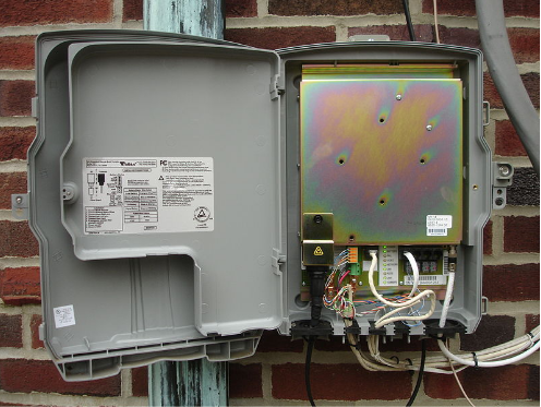
An open ONT box mounted outside on a brick wall.
Demarc Terminology
Plain Old Telephone Service (POTS)
Plain old telephone service (POTS) is the most basic type of phone service, commonly used in homes and small businesses today. These are typically used in conjunction with NIDs. While limited in capability, POTS is reliable and most often used for landline phones, alarms, and fax machines.
Digital Subscriber Line (DSL)
Digital subscriber line (DSL, originally called digital subscriber loop) allows for a computer to connect to the Internet using a telephone line. These allow for the use of Internet and phone at the same time, unlike older dial-up connections. While not as heavy-duty as T1 connections, they are considered adequate for home usage and small businesses. They will also require you to use a DSL filter to maintain compatibility with older POTS lines.
T1
T1 (T-1) is a type of digital phone service capable of supporting up to 28 digital voice lines or 48 VoIP lines. It can carry up to a total of 1.5 Mb of bandwidth. This type of line is very common for mid-sized businesses, allowing companies to minimize costs for per line voice connections, Internet connections, or connections to remote sites over a private network. T1 works by using two pairs of copper wire, one for sending signals and the other for receiving. The maximum distance of T1 is 655 feet (200 meters) past the demarc.
T1 can also be referred to as DS1 or DS-1 (Digital Signal 1). There are two variants of DS1 with T1 being the variant used in the United States. Introduced in 1962 by Bell System (AT&T), T1 is commonly used to this day.
Analog
An analog phone is the old school, traditional phone usually connected to a landline. These phones are limited compared to their newer, digital counterparts. Most analog phones today are found in businesses or places where they can be used as an emergency line, such as an elevator. While an analog phone only works with an analog signal, the use of a converter can allow them to be used with newer technology.
Analog phones do tend to have better sound than digital phones. It also costs less with phone companies to make analog calls. The downside here is that analog signals (usually) only work with a traditional phone you can plug into the wall. While it is possible to talk on a cell phone using an analog signal, few cell phones support it and it is often more trouble than it is worth. Analog signals are also voice only; they cannot send data like text messages or pictures. While they can be used wirelessly (like a home cordless phone), these have a very limited range.
Digital
Digital phones use signals similar to ones used by computers. The outgoing voice signal is broken up into data, sent through the phone lines to the person you are speaking with, and then changed back into a voice signal for them to hear. These are commonly used on cell phones as well as modern office phones.
Because the signal is being transmitted as data, a digital line has greater security than its analog equivalent. With the signal effectively being computer code, that data can be encrypted before it is sent down the line. Digital signals are also less prone to interference, lowering the chances of having problems like static or a weak signal. A phone (or any other device) set up for a digital signal will only work with a digital signal. If you are using it with an analog or VoIP connection, you will need a converter.
VoIP
Voice over Internet Protocol (VoIP, also referred to as broadband phone) is a phone that uses a computer network to communicate. VoIP is generally used on a private network to maintain clear sound quality on calls. While it is possible to use VoIP with a public network, it usually results in a lot of static and dropped calls. Depending on the service provider, you may be able to only call other VoIP users on your network or you may be able to call any phone number.
Talking through a computer eliminates the hassle of having an actual phone, but there are a few disadvantages as well. Unless your computer is using a backup battery, you will find yourself without a phone during a power outage. VoIP may or may not directly connect to 911 emergency services like a regular phone. This will depend on your service provider as well as your location and is a good thing to read up on before setting up a VoIP. VoIP phones will also only work with a VoIP signal; using an analog or digital signal with a VoIP phone will require a converter.
Quality of Service (QoS)
Quality of Service (QoS) is a function on VoIP networks to keep your calls clear. This feature gives your calls priority over any other network usage, such as Internet browsers, in order to maintain call quality. While most private networks set up QoS by default, it cannot be used on a public network. Without QoS enabled, VoIP calls can easily become bogged down by congestion in your network.
Power Over Ethernet (POE)
Power Over Ethernet (POE) is commonly used to provide VoIP phones with power, allowing the phones to function without a wall outlet. These are ethernet cables that can transmit power along with data. Along with VoIP phones, they are also used with IP cameras, wireless access points, network routers, and more.
Private Branch eXchange (PBX)
A Private Branch eXchange (PBX) is another name for a privately owned telephone system. This term commonly describes the set-up inside an office building, with desk phones and other lines hooked into the main line that actually goes to the demarc. Any basic office phone function, from transferring calls to using voice mail, likely utilizes PBX.
PBX is the type of phone system where you have to dial another number (usually 9 or 0) to make an outside call. The computer managing the functions of a PBX is called the Control Unit. Most companies utilize PBX as a cost saver, allowing users to avoid having to pay for an individual line for every single phone in the building.
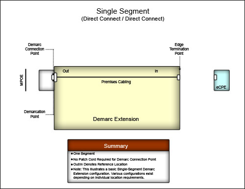
Demarc Extensions
A demarcation point extension (demarc extension) is the process of connecting your customer-premises equipment (CPE) to the Public Switched Telephone Network (PSTN), as defined by the FCC. Cabling from the demarc must extend to a wiring closet or data distribution system to integrate with your network. The exact details will depend on the demarcs location and your building’s layout.
A diagram displaying a basic demarc extension.
Demarc extensions, like demarcs themselves, have many names attributed to them. They can also be referred to as extended demarc, DMARC extension, CPE cabling, service interface extensions, circuit extension, inside wiring, or riser cabling.
Checking the Test Jack
If you notice problems with your line, such as no dial-tone or static, you can use your demarc for a little troubleshooting. This will help you determine where the problem is located and may save you a service call fee from your telecom provider.
Open up your demarc box (this will usually require a screwdriver) and look inside for a phone plug. This is what connects your lines to the Public Switched Telephone Network (PSTN).
Disconnect this line and hook up a standard corded telephone in its place to test the line. Listen for a dial tone and try making a call to see whether the line works.
If you are still experiencing issues, the source of the problem is somewhere in your building. That will mean the issue of fixing it lands on your shoulders.
If you plug the phone in and it works, that means your telecom provider is the one with faulty equipment. This will be the time to contact them, so they can begin repairs ASAP.
Any and every demarc is classified as the property of the telephone company. Any equipment extending from the box to your building will be your responsibility, but the demarc itself should be handled by your service provider in the event of equipment failure. Most demarcs are covered in warning labels saying something to the effect of “ISP Access Only”, so proceed at your own risk if you decide to check this yourself.
Anytime you notice issues with your signal, it could have a number of potential causes. In some cases equipment simply goes bad over time, although this is a fairly rare occurrence. There is also the possibility of damage, such as a neighbor accidentally cutting a line while digging or a rodent chewing through wires. Interference from other devices, like a newly installed alarm system, could also interfere with your building’s wiring.
History of Demarcs
Prior to 1984, the Bell System Companies (AT&T) held a monopoly on telecom systems and did not allow the use of third-party equipment. After an 8-year antitrust lawsuit against the company (United States v. AT&T), Bell System Companies was broken up into a number of smaller “Baby Bell” companies. Once the deregulation kicked in, demarcs began becoming commonplace as federal law now required local access providers to implement them.
Unfortunately, the division of Bell System Companies also eliminated the standardization of equipment. Over the next 13 years, multiple revisions would be made to the 1984 ruling. The first of which took place in 1990, when the demarc was more clearly defined by the FCC. They introduced the 12-inch rule which stated, “The demarcation point may be located within 12 inches of the point at which the wiring enters the customer’s premises.”
The Telecommunications Act of 1996 made major changes to telecommunication law, being the first of its kind since the Communications Act of 1934. The FCC stated that the amendment was intended to “let anyone enter any communications business – to let any communications business compete in any market against any other.” In layman’s terms, this revision allowed for the sale and usage of third-party equipment. It also legally included the Internet as a telecom service for the first time.
Finally, in 1997, the 12-inch rule was expanded with a little extra wording, “…or as near thereto as practicable.” Adhering to the 12-inch rule had been somewhat troublesome in some locations due to building layouts. This amendment made the task of installing and maintaining demarcs in accessible locations more feasible now that less red tape was involved.
While these later rulings helped move things along, we presently still lack a national standardization for demarc extensions. The lack of a rulebook has led to poor installation practices stemming from that confusion. Despite living in the Information Age, this crucial feature of Internet access is still plagued by connection losses, slow service, and untimely repairs.
Demarc Standardization (or Lack Thereof)
While changes to the law did break up a monopoly, one of the drawbacks was the loss of standardization for demarcs. With anyone and everyone able to manufacture and use personalized equipment now, there was no longer a list of rules that the industry as a whole agreed to follow. The Commercial Building Telecommunications Standard (ANSI/TIA-568.1-D), for example, does not actually discuss the demarc extension. This lack of definition has resulted in some facilities receiving fairly messy installs over the years, as efforts to restore standardization for demarc extensions are ongoing. A poorly installed demarc might not even be labeled properly, making finding the right circuit when a repair or new installation is needed costly in time, money, and manpower.
Cleaning up an existing demarc can be just as critical to business operations as installing a new one. If something goes wrong with an ethernet cable in an office, someone’s computer will lose network connectivity and that employee’s productivity will drop down to zero until the connection is repaired. If the something goes wrong with a demarc, that productivity drop will happen to everyone in the entire building.
Think of this as the same as taking your car in for preventative maintenance. You can get a quick, easy fix now or wait until something breaks and deal with that crisis when it happens. Obtaining and maintaining a clean, smoothly running system may cost a dollar now, but it will likely save you ten dollars down the road.
Installing Demarc Extensions the Right Way
Installation Preparation
Demarc extension installations have a few common problems associated with them. The most frequent issue for businesses is access. In an office environment, demarcs are commonly installed in small spaces like telecom rooms inside utility closets. Rooms like these tend to become cluttered, making it difficult for technicians to even reach the demarc, let alone work on it.
Another potential issue is coordination prior to the installation. Someone on-site will need to be ready to work with the technician, providing access to the right parts of the building. Some services related to demarc extensions, such as T1 installations, will also require prep work before the technician arrives. There will also need to be communication with your telecom provider so that technicians can test everything properly once the demarc extension is installed.
With a demarc extension running new cabling, you will want to make sure there is enough space available. If the new cables need to go through a hole in the wall that is already stuffed full of other lines, that will likely cause an issue. In older buildings, some existing cables may even be for old systems that are no longer in use.
Doing a little preparation will allow technicians to do their job quickly and efficiently, ultimately resulting in less downtime and getting your building up and running in a timely manner.
Installations Customized For You
Whether you are using a POTS, DSL, or T1 line, our installation team at INC Installs (INC) will prepare a customized plan for your facility. With each and every installation having unique needs, our services can range anywhere from simple cable extensions to full-service network integration. INC has experience performing demarc extensions in a variety of facilities including warehouses, offices, schools, shopping malls, and high-rise buildings.
Our technicians will run your cabling while neatly arranging and concealing the lines. These layouts are organized to be easily accessible for future use while remaining aesthetically pleasing. Taking demarc extensions a step further, our teams can also connect these new systems into your network.
For larger networks, systems exceeding the size used by a small business, it is often necessary to create structured-cabling solutions. Depending on the needs of your system, our technicians can connect the Main Distribution Frame (MDF, also called a shared telco closet) to Intermediate Data Frames (IDF) using 4-pair, 25-pair, 50-pair, 100-pair, 200-pair, or fiber optic cable. These can be arranged as individual horizontal distribution systems (to connect to individual workstations) or as a backbone distribution system that utilizes vertical distributions, for settings such as high-rise buildings or long hallways.
Once the new demarc extension is installed, our technicians can perform a test run once your telecom provider has made the new circuit live. Simple test signals will be sent through the lines to ensure all equipment is communicating properly. Our experienced technicians can work directly with the telecom company from your side to ensure that everything is working correctly.
To set up a new demarc extension, it may be necessary to install a router configured to receive data signals from a specific source. Our technicians are as fully skilled in this area of installation as they are with running new cabling and will make this process simple and clean.
The entire process of installing a demarc extension can seem daunting, but our experts will make the installation as fast and smooth as possible. If you have additional questions on this process, please call us directly at 888-519-9525 or request a quote here. Our team will work with you to customize your installation and ensure your demarc extension is up and running swiftly.
https://www.inc-installs.com/wp-content/uploads/2026/04/INC-Installs-Web-Logo.png00Patrick Giffordhttps://www.inc-installs.com/wp-content/uploads/2026/04/INC-Installs-Web-Logo.pngPatrick Gifford2018-08-16 10:17:252018-08-17 07:27:55Demarcation Point (Demarc)
Mankind has made significant bounds in technology and I was researching some information on the origins of telephone lines and cables. I came across Johann Philipp Reis. This man worked before any of the big names associated with the telephone, like Alexander Graham Bell. Here is an article I found on this forgotten man.
Johann Philipp Reis
The work of Reis predated that of Bell and Edison, and so he may well have invented the first telephone by some definitions. Unfortunately, due to technical problems, politics and commercial considerations, he did not receive the credit he was due during his lifetime.
Reis was born in 1834 in Gelnhausen , a little town in Germany. His father died early, and Reis was destined to become a farmhand, but his intelligence was noted by the local schoolmaster. He was sent off instead to Garnier’s Institute in Friedrichsdorf to further his education. He learned French and English and little other useful knowledge apart from what the school library offered. When he was fourteen he moved to Hassel’s Institute in Frankfort-am-Main. Here he learned Latin and Italian, this being considered appropriate education in those days. His interest in science began to show out, but it would not pay the bills. An uncle apprenticed him into the “colour trade”.
Reis continued to study in his own time, and took private lessons in mathematics and physics. He also attended the lectures on Mechanics run by Professor Bottger at the local Trade School. When his apprenticeship ended he moved to Frankfurt to Dr Poppe’s Institute. He privately taught other students Geography, which was not taught at the school, and found he enjoyed teaching. He also found the time to join the Physical Society of Frankfurt.
His first paper, “On The Radiation Of Electricity“, was submitted to the Annalen Der Physik journal in 1859. It was rejected, which was a blow to the sensitive young man.
Reis turned his attention to building a device to transmit sound by electricity. He started to achieve some success, and it is noted that the first words successfully transmitted were “the horse eats no cucumber salad”. The results were encouraging, and he submitted another article to the Journal in 1862. This was also rejected, but it is significant in that he called his device a “Telephon” – the first appearance of the name in connection with electrical sound transmission. His device was based on the theories of M. Charles Bourseil, a French telegraphist, who in 1854 suggested a device that would make or break an electrical current under the influence of a diaphragm. The make-or-break current would then generate a similar sound in a receiver. Bourseil stated prophetically “in a more or less distant future, speech will be transmitted by electricity“. He actually built such a device, but found its adjustment was critical and its results inconclusive, so he did not proceed with it.
Reis knew of the principle of the “Page Effect”, which later became known as Magnetostriction. An iron needle or rod surrounded by a coil of wire would be moved by a variable current flowing through the coil and produce a “tick” sound. A succession of ticks generated a tone, which Page called “Galvanic Music”. Reis used this principle to build a basic receiver, and attached the mechanism to part of a violin to act as a sounding board. His transmitter was carved out of a beer barrel bung in an approximation of the human ear. A sausage skin formed the diaphragm. A tiny strip of platinum glued to the diaphragm acted as one electrical contact, and another bead fixed to an adjusting screw as the other. The device worked, to everyones amazement. It is now held in the Reichs Post-Amt Museum in Berlin. It transmitted simple musical tones, but could not handle the complex waveforms of the human voice. He published his results in the Jahresbericht journal in 1861 after demonstrating it to the Physical Society of Frankfurt. It worked at the demonstration by means of constant critical adjustment. Reis recorded that “the consonants are for the most part tolerably distinctly reproduced, but the vowels not yet in an equal degree“.
Left: Second version, 1861
Left: Third version which briefly went into commercial pproduction by Albert. 1882.
Left: Final version, by Hauck.
Improvements followed in the second and subsequent models, but apart from a few muffled words here and there it was never a reliable transmitter of speech. The third and later models used a cubic block of wood bored out in a cone shape, with the diaphragm across the top. The small platinum strip was replaced by a centre contact held against the diaphragm by a metal tripod spring arrangement. Sound was fed to the diaphragm by a speaking tube. It was put into limited production by J Albert of Frankfurt and later by Hauck of Vienna.
Despite the Telephon’s less than impressive performance it was widely noticed in scientific circles. During its production, information and copies were sent abroad. It was demonstrated before many scientific societies, but the results were still generally disappointing.
“…The sounds transmitted by Reis’s telephone are rather weak and muffled. Moreover they do not perfectly preserve the timbre peculiar to the sounds imparted to the transmitter. Nevertheless they permitted differences in quality to be observed. Professor Bohn says that in the early experiments of 1864 the son of Privy Councillor Jhering of Giessen was found to be a better speaker through the telephone than most other persons, and that it was easy to distinguish the voice of a boy from that of a girl. Reis himself states that, when chords struck on the piano were transmitted, a person having a musical ear could in the majority of cases distinguish the various notes in the chord…” “The fundamental ideas of Reis were based on the construction of the human ear. He had set out with the direct intention of transmitting speech electrically, as he states in the opening sentence of his first paper on the subject, communicated in October 1861 to the Physical Society of Frankfurt-on-the-Maine. But he was at first baffled by the difficulty of finding a form of apparatus that could respond to all the various tones that are simultaneously used in speech……At last he saw that the human ear itself solved the problem, and furnished a sort of type of the requisite mechanism. His first experimental transmitter was therefore an “electric ear”. It is still preserved in the Patent Museum in Berlin….
From Electricity and Magnetism, by A Guillemin, published in 1891 by Macmillan, London and New York. Chapter 7 pages 688-693.
It was only after the introduction of Bell’s telephone as a practical device that the importance of his work was fully recognised. This was mainly as a result of the court cases that tried to annul Bell’s patent by citing Reis as the true inventor. When Antonio Meucci challenged Bell’s patent, he was able to append sixty one scientific articles citing Reis as the inventor of the telephone.
Amos Dolbear used Reis’ work to prove the validity of his own phone. When Bell brought the inevitable patent infringement suit, Dolbear set out to demonstrate in court that Reis’ 1860 telephone worked. This would make Bell’s patent invalid. The demonstration became an embarrassing disaster for Dolbear. Electricians, lawyers and learned Professors tried to coax speech out the reluctant Telephon, but all they could get from it was squeaks and muffled noises. One of Dolbear’s lawyers said in frustration “It can speak, but it won’t.”
Reis received some renown at this time, but since the invention did not appear to be proceeding anywhere it was gradually dismissed as a scientific curiosity or “philosophical toy”. Again, Reis was disappointed .
The weakness of all his models was the make-or-break nature of the circuit. Up to a point this actually worked, as a sort of loose-contact transmitter. As soon as the voice became loud the circuit would break and there would be no further transmission until a return spring reestablished the contact. These breaks destroyed the clarity of the speech, and also Reis’ claim to have invented a telephone. It was not until Berliner put an induction coil across the transmitter that the sound became loud enough and unbroken.
Berliner later used the loose-contact principle to produce his (workable) transmitter. The similarity between his design and Reis’ is unmistakable. The difference was that Berliner deliberately set out to use the loose-contact principle, while Reis bypassed it and stuck doggedly to make-or-break, overlooking the fact that his transmitter did actually work at low volume. He continued to stress make-or-break in his documentation. It was this that cost him the glory of being upheld as the telephone’s inventor in the U.S courts. In 1881 Judge Lowell of the U.S. Circuit Court of Massachussetts ruled “The deficiency was inherent in the principle of the machine …. A century of Reis would never have produced a speaking telephone by mere improvement in construction“. That about summed it up.
Prof. David Hughes found that by using carbon rods he could make a microphone that worked by variable pressure, and was far more sensitive than the Reis transmitter, but he found the same problem as Reis and Berliner – at high volumes the circuit failed as the carbon pencils broke contact. His work predated that of Berliner, so he was unaware of the beneficial effects of an induction coil.
It is interesting to note that both Bell and Edison later acknowledged Reis’ work as part of the inspiration for their own, once the court cases had settled down. In Britain, where Reis’ work was well known, Bell’s patent application was tactfully called “Improvements In Electric Telephony and Telephonic Apparatus“.
Reis’ health was failing with the onset of tuberculosis. He found it difficult to keep up his teaching duties, and work on the telephon was suspended. He died on January 14, 1874. Reis’ work and achievements were later suppressed by the Nazis because he was Jewish, and have only started to be acknowledged again in recent decades.
There are some interesting footnotes to Reis’ work. When the Western Union company realized that Bell’s telephone was starting to affect their revenue, they employed Edison to develop a competing phone for them. William Orton, the president of Western Union, gave Edison a translation of Reis’ work as a starting point for his research. Edison’s first carbon phone is very similar to that of Reis’ apart from Edison’s use of a carbon diaphragm. Orton later commented “I find it amusing that Bell is perceived as the man who spent his whole fortune defending his patent on the phone, when in fact all he did was spend his whole fortune patenting Philipp Reis’ work”. Ironic, and partly true.
A development of Reis’ phone went into commercial production for the Dakota Emner Telephone Company and the Aberdeen Telephone Company in the U.S. in 1866. It was probably based on the second model, the most robust and simplest to build. The little information surviving does not give much detail. The phones were made by John Zietlow, a German immigrant, and Charles Emner, an electrician and discharged convict turned real estate agent. The companies were quite successful in their area, and their telephones were never challenged legally by the Bell company. Zietlow’s modifications apparently worked very well.
The British Post Office later examined Reis’ phone and concluded that with very careful adjustment it would definitely transmit speech. Their engineers used a stepup transformer and a modern receiver, which gave some improvement to the Telephon’s low output (and confirmed its shortcomings). The BPO carried out its examination in 1932, and STC reexamined the transmitter in 1947. They confirmed the BPO’s findings. They did not publish their conclusions at the time as they were engaged in negotiations with AT&T, the Bell company. Although these experiments are interesting, they highlight the reasons the Reis Telefon did not work – a lack of continuity in the circuit, and when it did work the signal level was too low to be practical. The experiments are often used to “prove” that Reis’s Telephon did indeed work and he was the true inventer of the telephone. It did work, but in the Reis form it was impractical. In fairness, the science of coils and transformers had barely begun and Reis would not have had the technology available to him.It was left to other inventors like Bell and Berliner to overcome these problems and produce a reliable workable phone.
In belated recognition of a worthy man, the Philipp Reis Prize is awarded each two years since 1987 to a promising German inventor.
https://www.inc-installs.com/wp-content/uploads/2026/04/INC-Installs-Web-Logo.png00Patrick Giffordhttps://www.inc-installs.com/wp-content/uploads/2026/04/INC-Installs-Web-Logo.pngPatrick Gifford2015-06-11 15:00:352019-04-03 15:02:25The Forgotten Johann Philipp Reis


![Reis Telephon 1863 [from Du Moncel, "Le Tlphone", p. 15]](https://web.archive.org/web/20150612190406im_/https://www.inc-installs.com/wp-content/uploads/2015/06/Reis3-300x262.jpg)
