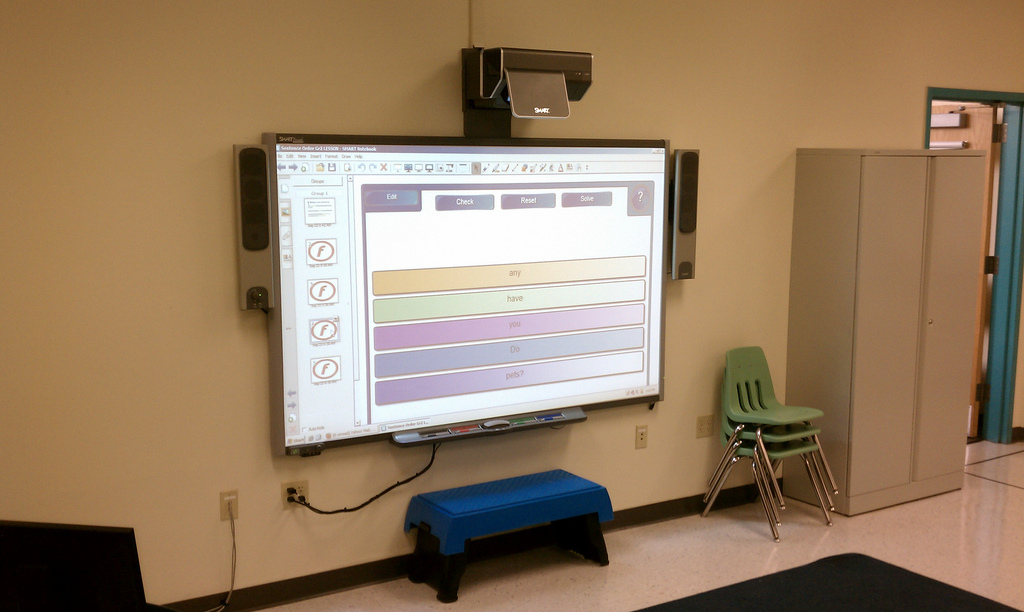
SMART Board Installation

In educational settings, SMART boards have become increasingly popular over the last 15 years. Being able to support media and writing through direct user interaction, a SMART board essentially combines chalkboards and projectors together for classrooms, meeting rooms, and more. Taking full advantage of this modern technology has been shown to have numerous benefits for student learning.
“SMART board” is a common name for an interactive whiteboard. Originally named after the Smart Technologies Corporation, the two names have become synonymous over the years. They can also be referred to by other brand names, such as Promethean ActivBoards, or other general terms like “digital presenters”. Regardless of what you call them, the main function of each device is by-and-large the same.
There are different variations of SMART boards on the market. While they all have similar functionality, the way each unit functions can vary. Modern SMART boards come in four different varieties: infrared, resistive, electromagnetic, and ultrasonic.
Infrared
Infrared SMART boards use a computer and projector. The board can be made from any material so long as it is a flat surface. This flexibility allows infrared boards to be installed on top of existing dry erase boards in older classrooms. The projector emits infrared light onto the board; when something touches the board (a pen, finger, or any other object), the system detects that the infrared light is not touching that spot and translates it into a mouse click.
Resistive
Resistive SMART boards are made using a special elastic material along with a metal plate. The elastic stretches over the backplate for protection. When the projector is turned on and the board is touched, the board registers that touch as a mouse click. While the board itself is a bit more heavy-duty than other SMART board options, no other special tools are needed for this type of unit.
Electromagnetic
Electromagnetic SMART boards are solid and contain an array of wires just underneath the surface. These boards come with a special pen made from a material that alters the electrical signals running through the wires. Each alteration tells the board it is being touched; a light touch allows users to write while pressing down on the board triggers a mouse click.
Ultrasonic
Ultrasonic SMART boards use a combination of ultrasonic positioning and infrared light technology. Like electromagnetic boards, ultrasonic boards require the use of a special pen. The board utilizes a combination of light and sound signals to detect when the pen makes contact. Like infrared boards, ultrasonic boards can be displayed on any flat surface.
Pre-Installation Tasks

Each installation is unique, but they all start with the same thing: a site survey. Measuring the scope of your project is critical in determining what tools and equipment will be needed. Setting up a single SMART board in an office meeting room will be a very different project from installing units in every classroom for a newly constructed school. For simple projects like working with existing hardware, a phone call can be all it takes to start the project planning. For more detailed projects, a technician may need to come out and examine the site.
After the survey is complete, our team will formulate a custom plan for your facility. Factors such as the type of SMART board being used, distance between the projector and board, and how the system hardware will interconnect will all be factored in here. Prior to the installation, our team can ship HDMI cables, mounts, brackets, and other necessary equipment directly to the job site. On the day of the installation, make sure there is a way for the installer to access the property. Ideally, this will involve having someone on-hand to let them in. This representative should also be able to point the installer to the work area as well.
Completing the Installation

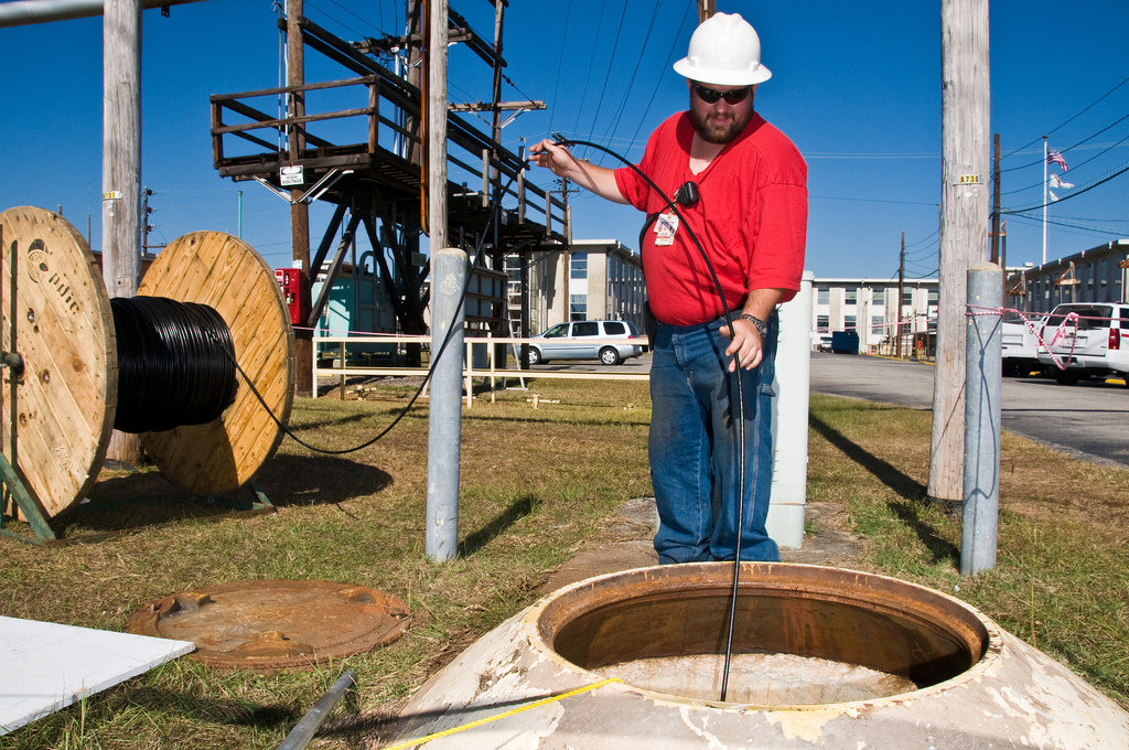
With the materials already onsite, our technicians will unpackage everything and start prepping the walls by cutting holes for cables and hanging brackets/mounts as needed. Then the hardware will be mounted and connected, with cables being run through the walls, floors, and/or ceiling as needed. Once everything has been cleanly connected, the system will be tested to check functionality. After that, it is a simple matter of cleaning up the area and your new SMART board will be ready to go.
At INC, we perform SMART board installations for schools, universities, business offices, churches, convention centers, and more. A properly installed SMART board not only looks crisp and clean but will also provide key functionality to day-to-day operations. Whether a SMART board is being installed from scratch or tacked onto existing equipment, INC is ready to get the job done right.
If you have additional questions on this process, please call us directly at 888-519-9525 or request a quote here. Our team will work with you to prepare your custom installation project.